
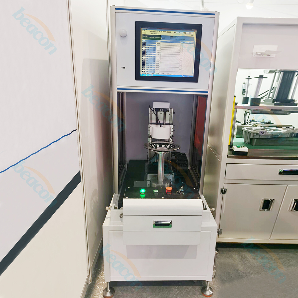

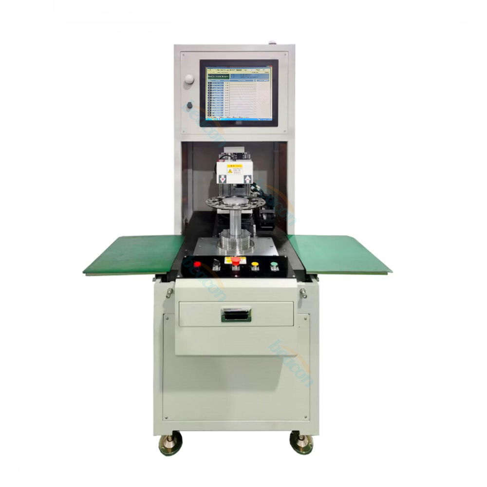
BD101 Semi-Automatic Laser brake drum disc lathe cutting machine configured with Taiwan Advantech industrial control computer,brand I/O board,and motion control board,automatic removal of brake disc faces and grooves
0086-18253885135
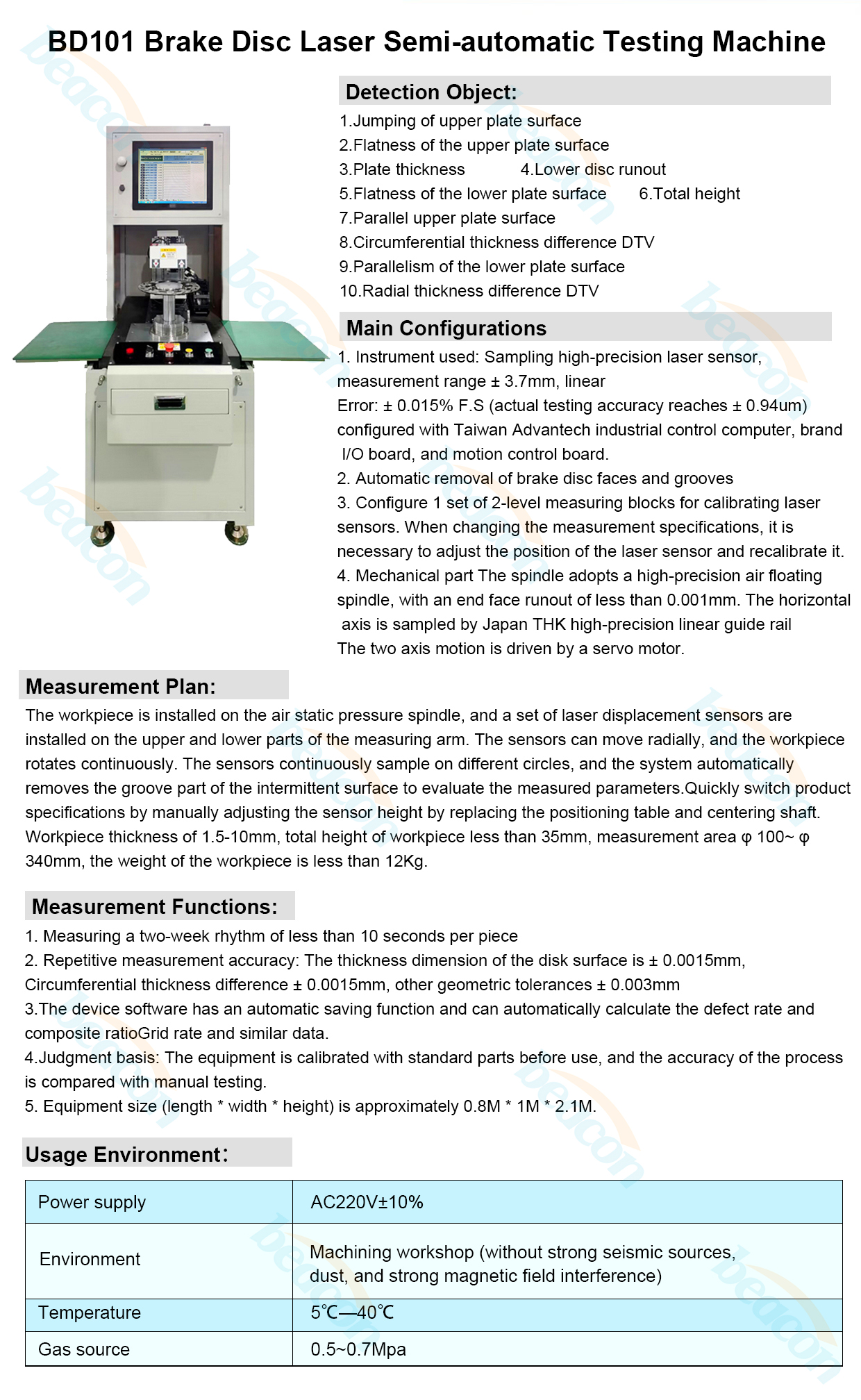
1:Detection object
Jumping of upper plate surface
2:Main configurations
2.1 Instrument used: Sampling high-precision laser sensor, measurement range ± 3.7mm, linear
Error: ± 0.015% F.S (actual testing accuracy reaches ± 0.94um) configured with Taiwan Advantech industrial control computer, brand I/O board, and motion control board.
2.2 Automatic removal of brake disc faces and grooves
2.3 Configure 1 set of 2-level measuring blocks for calibrating laser sensors. When changing the measurement specifications, it is necessary to adjust the position of the laser sensor and recalibrate it.
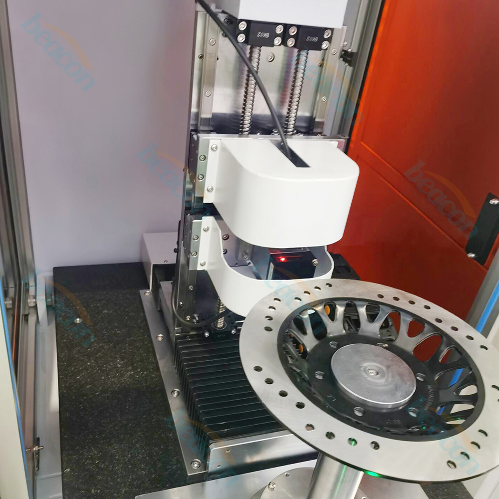
2.4 Mechanical part
The spindle adopts a high-precision air floating spindle, with an end face runout of less than 0.001mm. The horizontal axis is sampled by Japan THK high-precision linear guide rail
The two axis motion is driven by a servo motor.
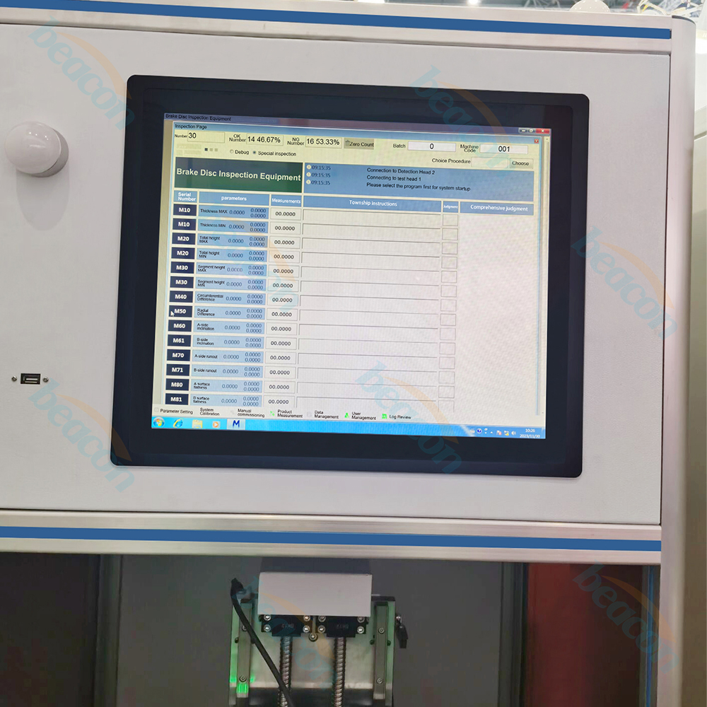
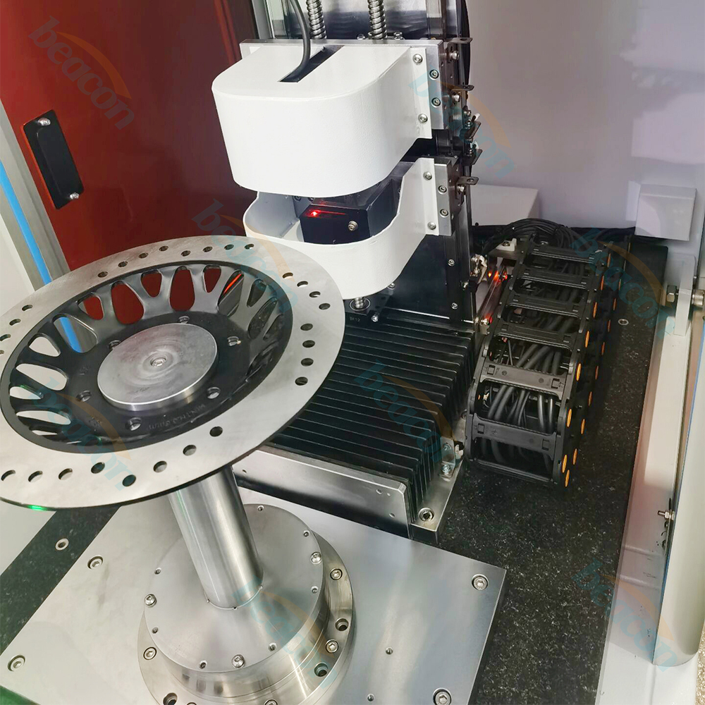
3: Measurement plan:
The workpiece is installed on the air static pressure spindle, and a set of laser displacement sensors are installed on the upper and lower parts of the measuring arm. The sensors can move radially, and the workpiece rotates continuously. The sensors continuously sample on different circles, and the system automatically removes the groove part of the intermittent surface to evaluate the measured parameters.
Quickly switch product specifications by manually adjusting the sensor height by replacing the positioning table and centering shaft.
Workpiece thickness of 1.5-10mm, total height of workpiece less than 35mm, measurement area φ 100~ φ 340mm, the weight of the workpiece is less than 12Kg.
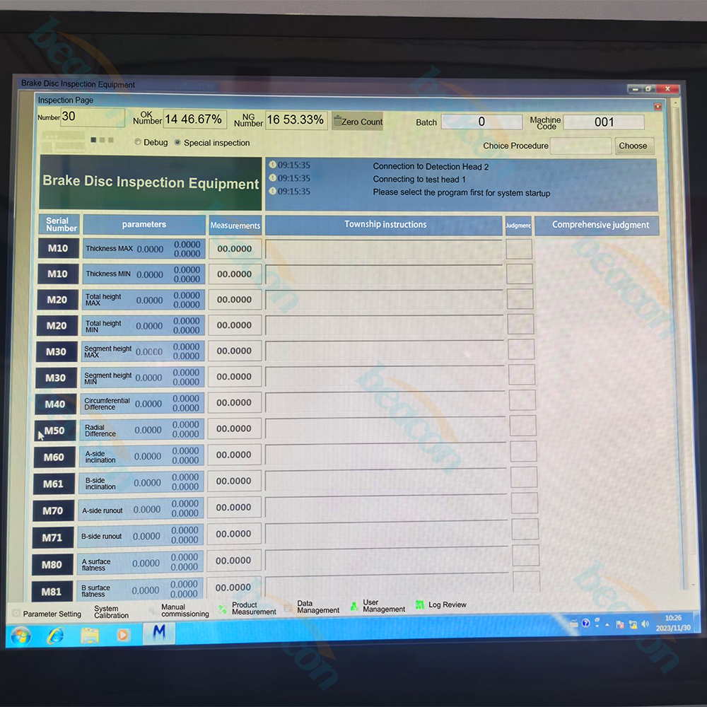
4: Measurement functions
4.1 Measuring a two-week rhythm of less than 10 seconds per piece
4.2 Repetitive measurement accuracy: The thickness dimension of the disk surface is ± 0.0015mm,Circumferential thickness difference ± 0.0015mm, other geometric tolerances ± 0.003mm
4.3 The device software has an automatic saving function and can automatically calculate the defect rate and composite ratio Grid rate and similar data.
4.4 Judgment basis: The equipment is calibrated with standard parts before use, and the accuracy of the process is compared with manual testing.
4.5 Equipment size (length * width * height) is approximately 0.8M * 1M * 2.1M.
 English
 Русский
 Español